Flow
Flow Networks are a general framework for data processing. Currently, they are mainly used for feature extraction and alignment processing.
For the development of new Flow nodes, see these slides.
Node
Nodes are the basic units of Flow
A node processes packets of data.
A node can have zero, one, ore more inputs and outputs called port
An output port of a node can be connected to input ports of one ore more nodes.
Ports can have names
If a port has more than one input / output port, it must have a name
A node must have a (unique) name
The processing performed by a node is either defined by a build-in Flow Node or by a self defined #Network
Example 1
We start with an abstract example:
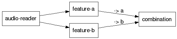
the node audio-reader has no input port and one output port
the output port of audio-reader is connected to the input ports of the nodes feature-a and feature-b
every data packet written by audio-reader is send to both feature-a and feature-b
feature-a and feature-b have one input and one output port
the node combination has two input ports named a and b
Network
A set of nodes connected by links forms a network.
A network can be used as node itself
So, it can define input and output ports
A network can be used as a node in another network
A network has a name. If no name is defined, the default name is network.
Example 2
First, we define a network consisting of two nodes, which has an input port in and an output port out:

This network is then included in a second network as a node called lda:

The first two nodes are like the one in Example 1: An input-less node audio-reader whose data is processed by a node feature-a.
The data packets produced by feature-a are sent to the input port in of the network defined above.
The output port out of the (network-) node lda is forwarded to the output port features of the second network
Flow File
Flow networks are defined in XML files. The preferred file extension is .flow
We explain the structure of Flow files by examples. A complete file format specification can be found in Flow File Format Specification.
The network shown in Example 1 can be defined as follows:
<network>
  <node name="audio-reader" filter="some-audio-reader"/>
  <node name="feature-a"    filter="my-special-feature"/>
  <node name="feature-b"    filter="my-other-feature"/>
  <node name="combination"  filter="feature-vector-combination"/>

  <link from="audio-reader" to="feature-a"/>
  <link from="audio-reader" to="feature-b"/>

  <link from="feature-a"    to="combination:a"/>
  <link from="feature-b"    to="combination:b"/>
</network>
As stated above, this is an abstract example. So, the nodes shown do not really exist.
The root element of a network is <network>. In this example, its name is network, because no name is defined explicitly.
Nodes are defined with the tag
<node>.The name of a node is defined with the attribute name
The node type is defined with the attribute
filterA link between two ports is defined by the tag
<link>, its start and end points are defined with the attributes from and to respectively.The port names in the from and to attributes of a link are of the form
node-name:port-name. If no port name is given, the default port is assumed.
The networks in Example 2 would be defined in this way:
<network name="lda">
  <in name="in"/>
  <out name="out"/>

  <node name="sliding-window" filter="signal-vector-f32-sequence-concatenation"
        max-size="9" right="4" margin-condition="present-not-empty" expand-timestamp="false"/>
  <link from="lda:in" to="sliding-window"/>

  <node name="multiplication" filter="signal-matrix-multiplication-f32" file="$(lda-file)"/>
  <link from="sliding-window" to="multiplication"/>

  <link from="multiplication" to="lda:out"/>
</network>
This network gets a name: lda
The input and output ports of the network are defined by
<in>and<out>tags respectively.The input port(s) of the network are referenced by
network-name:port-name. In the above file:lda:inandlda:out.Parameters of a node can be given as attributes in the
<node>tag.The values of the parameter can be either fixed, as for node
sliding-windowor configurable, as for nodemultiplicationThe configurable parameters can be set by the Configuration mechanism.
How to include other flow files can be seen in the definition of the second network of Example 2:
<network>
  <out name="features"/>
  <param name="input-file"/>
  <param name="start-time"/>
  <param name="end-time"/>

  <node name="audio-reader" filter="audio-input-file-$(audio-format)"
        file="$(input-file)" start-time="$(start-time)" end-time="$(end-time)"/>

  <node name="feature-a" filter="some-node"/>
  <link from="audio-reader" to="feature-a"/>

  <node name="lda" filter="lda.flow"/>
  <link from="feature-a" to="lda:in"/>

  <link from="lda:out" to="network:features"/>
</network>
A network can have parameters, too. They are defined by
<param>tags.The parameters are set by either a network that includes this network or by the application that uses this network.
The network parameters can be used like every other configurable variable in the network. See node
audio-readerThe node
audio-readerin this example is of a configurable type: Its filter attribute is a combination of a fixed string and a configurable item. If the configuration would have an resource*.audio-format = wav, then a node of typeaudio-input-file-wavwould be used.The inclusion of other networks is done by specifying the file name of the network definition file. The filename can contain full paths.
Serialization of generated Flow network
You can let Flow dump the network it has built into a single .flow file for debugging. Just provide the network with the parameter flow-dump-channel.channel and define the channel parameters, e.g.
Example 3
[*.network_to_dump]
flow-dump-channel.channel    = dump-channel

[*.channels]
dump-channel.file            = my_network.dump.flow
dump-channel.append          = false
dump-channel.encoding        = UTF-8
dump-channel.add-sprint-tags = false
Then run a tool that will built the network and look for the file my_network.dump.flow once it’s done (the serialization is performed in the destructor).
Visualization of a Flow network
Use the tool flowdraw.py (requires “dot” from the Graphviz package).
src/Tools/Flow/flowdraw.py file.flow [plot.png]